In our previous lesson, we learned that connecting an output back to an input creates a feedback loop. This loop allows a circuit to "remember" a state. However, a simple loop isn't very useful if we can't change the value it is holding. To build a real computer, we need a way to "write" a new value into memory and "erase" it when we are done.
The SR Latch is one of the most basic types of digital memory. The S stands for Set (making the value 1), and the R stands for Reset (making the value 0). By using two logic gates together, we can create a circuit that stays in a specific state until we tell it to change.
Before we look at the whole circuit, let's quickly remember how a NOR gate works. A NOR gate is essentially an OR gate with an inverter at the end.
The rule for a NOR gate is simple: it outputs a 1 only if both inputs are 0. If even one input is a 1, the output immediately becomes 0.
| Input A | Input B | Output |
|---|---|---|
0 | 0 | 1 |
0 | 1 | 0 |
1 | 0 | 0 |
1 | 1 | 0 |
We will use two of these gates to build our memory cell.
To make an SR Latch, we connect two NOR gates in a cross-coupled pattern. This means the output of the top gate is wired to one of the inputs of the bottom gate. Similarly, the output of the bottom gate is wired back to one of the inputs of the top gate.
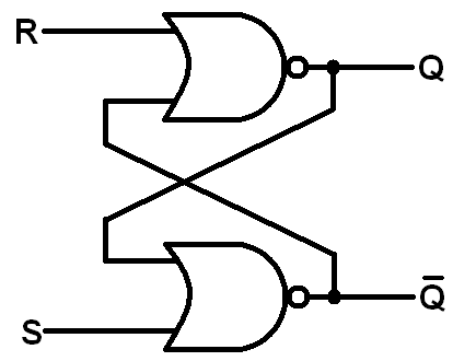
This creates a criss-cross shape in the middle of the circuit. In a standard setup:
- The top
gateprovides the mainoutput, which we call Q. - The bottom
gateprovides the oppositeoutput, called Not-Q. - In a healthy
circuit, these twooutputsshould always be opposites. IfQis1,Not-Qshould be0.
The "magic" happens when we use the two remaining inputs to control the circuit. Let's look at how we change the stored bit.
The Reset Action (R=1, S=0)
When you turn the Reset input to 1, the top NOR gate sees a 1. Because of how NOR gates work, any 1 input forces the output to 0. Therefore, Q becomes 0. This 0 travels down to the bottom gate. Since the Set input is 0 and the feedback from Q is now 0, the bottom gate sees two 0s and outputs a 1. So, Not-Q becomes 1.
The Set Action (S=1, R=0)
When you turn the Set input to 1, the bottom gate sees a 1 and forces its output (Not-Q) to 0. This 0 travels up to the top gate. If the Reset input is 0, the top gate now sees two 0s and outputs a 1. Therefore, Q becomes 1. You have successfully "set" the memory to 1.
You have now learned how to build a basic memory cell using two NOR gates. Here is a summary of the SR Latch behavior:
| S (Set) | R (Reset) | Q (Output) | State Description |
|---|---|---|---|
0 | 0 | No Change | Hold: Remembers the last value. |
1 | 0 | 1 | Set: Stores a 1. |
0 | 1 | 0 | Reset: Stores a 0. |
1 | 1 | 0 | Invalid: Both outputs become 0; avoid this! |
Now it is your turn to practice. In the following exercises, you will use the CodeSignal IDE to build this circuit yourself, observe the feedback loop in action, and see how the Hold state maintains information.
