Welcome back to 3D Worlds and Matrix Transformations! Having completed three foundational lessons, we've mastered the art of dynamic transformations and can now animate objects in real time using GPU uniforms. Our spinning square has served us well, but it's time to make a dramatic leap: transitioning from flat, 2D-looking graphics to true 3D perspective rendering.
In this fourth lesson, we'll implement a complete 3D camera system by introducing view and projection matrices alongside our existing model matrix. We'll replace our simple square with a colorful 3D cube and position a virtual camera to observe it from a realistic perspective. By the end of this lesson, we'll have a proper 3D scene with depth, perspective distortion, and all the visual cues that make objects appear truly three-dimensional rather than flat shapes rotating on a screen.
While our previous rotating square demonstrated dynamic transformations, it still appeared fundamentally flat because we were viewing it through an orthographic projection. In orthographic projection, objects maintain the same size regardless of their distance from the camera, which creates an unrealistic, engineering-drawing-like appearance.
Perspective projection mimics how our eyes actually see the world: objects farther away appear smaller, parallel lines converge toward vanishing points, and depth becomes visually apparent. This is the difference between looking at a technical blueprint and looking through a window at the real world.
To achieve true 3D perspective, we need three distinct transformation stages working together: the model matrix positions and orients our object in 3D space, the view matrix represents our camera's position and orientation, and the projection matrix defines how the 3D world gets flattened onto our 2D screen with realistic perspective distortion.
Modern 3D graphics use a standardized three-matrix transformation pipeline that converts object coordinates through several coordinate spaces before reaching the screen. Each matrix serves a specific purpose in this chain of transformations.
The model matrix transforms vertices from their local object space into world space, positioning and orienting the object within our 3D scene. The view matrix then transforms from world space into camera space, essentially moving the entire world relative to our camera's position and orientation. Finally, the projection matrix transforms from camera space into clip space, applying perspective distortion and defining what portion of the 3D world becomes visible on our 2D screen.
This pipeline approach provides tremendous flexibility: we can move objects independently with their model matrices, position our camera anywhere in the world with the view matrix, and adjust our viewing frustum with the projection matrix, all without affecting each other.
The view matrix represents our virtual camera's position and orientation in the 3D world. Rather than moving the camera around the scene, we actually move the entire world in the opposite direction relative to the camera, which remains at the origin of its own coordinate system. So when the camera "moves right", everything in the world is actually translated to the left by the same amount.
The glm::lookAt() function creates a view matrix using three intuitive parameters: the camera's world position, the point we want to look at, and the up direction vector. Here, we position our camera 3 units away from the origin along the positive Z-axis, looking back toward the center where our cube will be positioned.
The up vector (0, 1, 0) ensures our camera remains level with the Y-axis pointing upward. This function internally calculates the right, up, and forward vectors for the camera and constructs the appropriate transformation matrix to achieve the desired viewing angle.
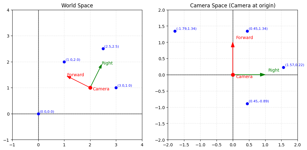
For simplification, imagine we have a 2D world with four points and a camera positioned somewhere in that world. World space represents the global coordinate system where all objects have fixed positions.
When we apply the view matrix transformation, we don't actually move the camera — instead, we transform the entire world so that the camera becomes the new origin (0,0) and the world coordinates are redefined relative to the camera's position and orientation. This creates camera space (also called view space), where everything is positioned relative to where the camera is looking.
The projection matrix defines our viewing frustum: the 3D region of space that becomes visible on screen. For realistic perspective, we use a perspective projection that makes distant objects appear smaller than nearby ones.
The glm::perspective() function requires four critical parameters that define our viewing volume. The field of view (FOV) determines how wide our viewing angle is, similar to a camera lens — a 45-degree FOV provides a natural viewing angle similar to human vision. The aspect ratio matches our window's width-to-height ratio to prevent distortion of our rendered objects.
The near plane defines the closest distance at which objects remain visible (0.1 units), while the far plane sets the maximum visible distance (100 units). Objects closer than the near plane or farther than the far plane will be clipped and won't appear in our final image, helping optimize rendering performance by eliminating unnecessary geometry.
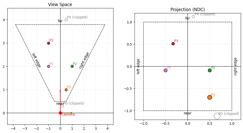
Again, in our 2D world, this time with our view frustum on the left. The near plane is positioned at 0.5 units from the camera, and the far plane is at 3.8 units. The field of view (FOV) is set to 90 degrees.
Notice how P0 and P4 fall outside the visible range — P0 is closer than the near plane and P4 is farther than the far plane, so both will be clipped and won't appear in our final NDC (normalized device coordinates) frame.
Points P3 and P5, which appear parallel to each other in camera space, become shifted in NDC due to the perspective transformation — objects farther from the camera (near the far plane) experience more dramatic positional changes. Conversely, points P1 and P2, which lie along the same ray extending from the camera position, end up parallel in NDC space because they maintain their angular relationship relative to the camera's center of projection.
An important consideration when working with projection matrices is their dependency on the framebuffer's aspect ratio — as the window dimensions change, our projection matrix must adapt accordingly to maintain proper proportions.
When users resize the application window, we must therefore update our projection matrix to maintain the correct aspect ratio and prevent distortion. A callback function detects resize events and triggers projection matrix recalculation.
The framebuffer callback updates our stored window dimensions and sets a flag indicating that the projection matrix needs recalculation. We also update the OpenGL viewport to match the new window size, ensuring our rendered image fills the entire window properly.
In the main render loop, we check for projection updates and recalculate the projection matrix with the new aspect ratio. This maintains the same field of view and depth range while adapting to the window's new proportions, preventing our 3D objects from appearing stretched or compressed when the window shape changes.
Our vertex shader must now handle all three transformation matrices in the correct order. The transformation pipeline flows from model space through world space and camera space to finally reach clip space.
The matrix multiplication order is crucial and must be read from right to left: first, uModel transforms the vertex from object space to world space, then uView transforms from world space to camera space, and finally, uProjection applies perspective transformation to reach clip space.
This single line of mathematics performs the entire 3D-to-2D transformation that makes perspective rendering possible. The GPU executes this calculation efficiently for every vertex in parallel, making real-time 3D graphics feasible even with complex geometry containing thousands of vertices.
Our render loop must now provide values for all three transformation matrices. We obtain uniform locations for each matrix and update them appropriately during rendering.
The view and projection matrices typically remain constant throughout our render loop, while the model matrix continues to animate as in our previous lesson. However, we must upload all three matrices to the GPU since the shader expects all uniforms to have valid values.
Each call to glUniformMatrix4fv() transfers a complete 4×4 matrix from CPU memory to GPU uniform memory, where the vertex shader can access it during vertex processing. The parameters specify which uniform to update, how many matrices to upload (1), whether to transpose the matrix (GL_FALSE), and a pointer to the matrix data.
To truly showcase our new 3D perspective system, we need genuine 3D geometry. Let's replace our flat square with a colorful cube that has actual depth and volume.
Our cube consists of 8 vertices positioned at the corners of a unit cube centered at the origin. Each vertex includes both 3D position data and RGB color information, creating a vibrant, multi-colored cube where each corner displays a distinct color.
The front face vertices have positive Z coordinates (0.5), while the back face vertices have negative Z coordinates (-0.5), giving our cube actual depth along the Z-axis. This depth will become visually apparent once we apply perspective projection, as the front and back faces will appear at different distances from our camera.
A cube requires 12 triangles (2 per face) to properly define its 6 faces. We use an index buffer to efficiently specify which vertices form each triangle without duplicating vertex data.
Each group of six indices defines two triangles that form one complete face of the cube. The winding order (clockwise or counterclockwise) determines which side of each triangle faces outward, affecting how lighting and backface culling will work in more advanced rendering scenarios.
Notice how we reference the same vertices multiple times: vertex 0 (front bottom left) appears in the front, left, and bottom faces since it's a shared corner. This index-based approach is much more memory-efficient than duplicating vertex data for each face.
With true 3D geometry, we need depth testing to ensure that closer surfaces appear in front of farther ones. Without depth testing, triangles would be drawn in the order they appear in our index buffer, potentially causing distant faces to incorrectly appear in front of nearby faces.
GL_DEPTH_TEST enables the depth buffer, which stores the depth value of each pixel on the screen. When rendering a new fragment, OpenGL compares its depth to the stored value and only draws the fragment if it's closer to the camera than what's already been rendered there.
We must also clear both the color buffer and the depth buffer each frame using the combined flag GL_COLOR_BUFFER_BIT | GL_DEPTH_BUFFER_BIT. The depth buffer needs to be reset to its maximum value each frame so that depth comparisons work correctly for the new frame's geometry.
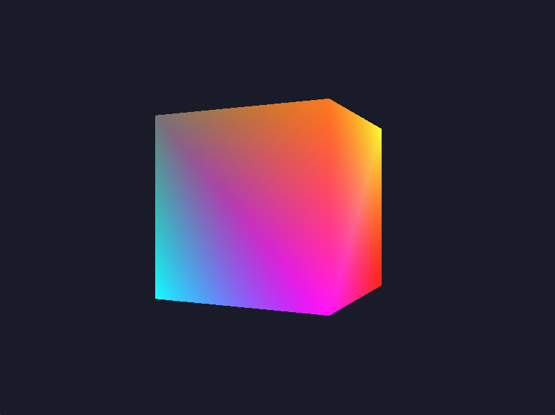
When we run our application, we see a dramatic transformation: our flat rotating square has become a vibrant, three-dimensional cube that spins with realistic perspective distortion. The cube appears to have genuine depth and volume, with faces that recede into the distance becoming visibly smaller, while closer faces appear larger and more prominent.
The different colored faces help emphasize the 3D effect as they rotate into and out of view, creating a mesmerizing display of perspective projection in action. The depth testing ensures that front faces correctly occlude back faces as the cube rotates around its center, maintaining proper depth relationships throughout the animation.
This represents our first complete 3D rendering system with proper camera positioning, perspective projection, and depth handling — all the essential components needed for realistic 3D graphics that truly convince the eye of three-dimensional depth and volume.
We've successfully created our first true 3D perspective rendering system! By implementing view and projection matrices alongside our existing model transformations, we've built a complete graphics pipeline that transforms flat geometry into convincing three-dimensional scenes. Our colorful cube now rotates with realistic perspective distortion, depth relationships, and all the visual cues that characterize authentic 3D graphics.
This lesson represents a major milestone in our journey through 3D graphics programming. We've learned how the three-matrix transformation pipeline works together to create perspective rendering, implemented a proper camera system with GLM's intuitive functions, and handled the complexities of 3D geometry with depth testing and dynamic window resizing. The practice exercises ahead will let you experiment with different camera positions, projection settings, and 3D objects, giving you hands-on experience with the powerful 3D rendering foundation we've just constructed.
