In our previous lessons, we built the D Latch. You saw that when the Enable (or Clock) signal is high, the latch is "open." In this state, the output Q follows the input D exactly.
Engineers call this transparency. Think of a latch like a window with a shutter. When the shutter is open (Enable is 1), you can see everything happening outside. If a bird flies by the window, the view changes instantly. In digital circuits, this is actually a problem. If your data input D flickers or changes slightly while the clock is high, that "noise" travels straight to the output.
In complex computers, we need memory that only changes at one specific moment, rather than staying "open" for a long period. This prevents errors from spreading through the system.
To solve the transparency problem, we move from level-sensitive circuits to edge-triggered circuits.
A clock signal is a square wave that constantly flips between 0 and 1. Instead of looking at the level (whether the signal is currently at 1), an edge-triggered circuit looks for the edge — the exact split second the signal transitions.
| Term | Meaning | Visual |
|---|---|---|
| Rising Edge | The moment the clock jumps from 0 to 1. | ⤴️ |
| Falling Edge | The moment the clock drops from 1 to 0. | ⤵️ |
| Level | The entire time the clock stays at 1. |  ̄ |
By using the Rising Edge, we ensure the memory only captures data for a fraction of a second. Imagine taking a photo with a camera. You don't want the shutter to stay open for five minutes (that would be a blurry mess); you want it to click open and shut instantly to capture one clear image. This is what a Flip-Flop does.
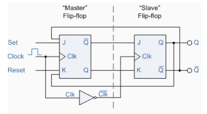
So, how do we build a circuit that only triggers on an edge? We use a Master-Slave design. This involves connecting two latches in a row but controlling them with opposite clock signals.
Imagine a space station airlock with two doors:
- The Master Latch (the first door): When the clock is
0, the first door is open. TheMasterlatch captures the current input data from the outside. However, the second door (theSlave) is locked shut, so the data can't reach the output yet. - The Slave Latch (the second door): When the clock flips to
1, the first door slams shut (locking the data in), and the second door opens. The data stored in theMasteris now passed to theSlaveand appears at the outputQ.
Because the two doors are never open at the same time, the input can never "race" all the way through to the output. The data is handed off only when the clock state changes. This creates the edge-triggering effect we need.
The D Flip-Flop is the most common memory component in modern electronics. It combines the "no-forbidden-states" logic of the D Latch with the Master-Slave timing we just discussed.
In a digital circuit, the Clock signal acts as the ultimate gatekeeper. While a simple latch allows data to flow through as long as the enable signal is high, a true D Flip-Flop uses its internal two-stage structure to ensure that the output Q only updates at the exact moment the clock transitions from 0 to 1. This creates a reliable "snapshot" of the input data.
By using D Flip-Flops, you can chain hundreds of memory units together. Since they all update only on the "click" of the clock, they stay perfectly synchronized. This predictable behavior is exactly how the processors in your computer or phone handle billions of operations per second without getting their data mixed up.
In this lesson, we upgraded our understanding of memory from simple latches to high-precision flip-flops. Here is a quick recap:
- Latches are "level-sensitive" (transparent), meaning they stay open as long as the clock is high.
- Flip-Flops are "edge-triggered," meaning they only capture data at the exact moment the clock changes.
- Master-Slave design uses two stages to prevent data from leaking through the circuit.
- The D Flip-Flop is the standard building block for stable, synchronized digital memory.
Now, it's time to head over to the practice section! You will get hands-on experience building these circuits and observing how the timing of the clock signal changes how data is stored.
