Over the past four lessons, you've built a capable ray tracer that can render realistic scenes with smooth antialiasing, natural lighting through path tracing, and two fundamental material types. Your Lambertian diffuse materials scatter light randomly to create matte surfaces like chalk or unfinished wood, while your metal materials reflect light in a mirror-like way to simulate shiny surfaces like polished chrome or brushed aluminum. These two material types already give you considerable expressive power, allowing you to create scenes with rich visual variety and realistic material interactions.
However, if you look around the real world, you'll notice an important class of materials that your ray tracer cannot yet render: transparent materials. Think about a glass window, a crystal vase, a water-filled drinking glass, a diamond ring, or even ice cubes in a beverage. These materials have a distinctive appearance that sets them apart from both matte and metallic surfaces. They don't simply scatter light like diffuse materials, nor do they just reflect it like metals. Instead, transparent materials do something more complex: they both reflect light from their surfaces and transmit light through their volume, bending the transmitted light as it passes through.
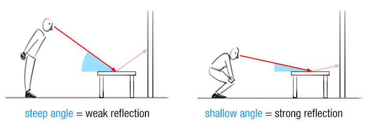
This dual behavior creates the characteristic appearance of glass and other transparent materials. When you look at a windowpane, you can see through it to objects on the other side, but you can also see faint reflections of objects on your side. The balance between transmission and reflection changes depending on the viewing angle. When you look straight through a window, you see mostly the transmitted light with only faint reflections. When you look at a window from a steep angle, the reflections become much stronger and the window starts to look almost mirror-like. This angle-dependent behavior is called the Fresnel effect, and it's one of the key characteristics that makes transparent materials look realistic.
The bending of light as it passes through transparent materials is called refraction, and it's responsible for many familiar optical effects. Refraction is why a straw appears to bend when you put it in a glass of water, why objects look distorted when viewed through a curved glass surface, and why diamonds sparkle with such brilliance. Different materials bend light by different amounts, characterized by a property called the refractive index. Air has a refractive index close to one, water is about 1.33, typical glass is around 1.5, and diamond is approximately 2.4. The higher the refractive index, the more the material bends light, and the more dramatic the optical effects become.
Understanding Refraction and Snell's Law
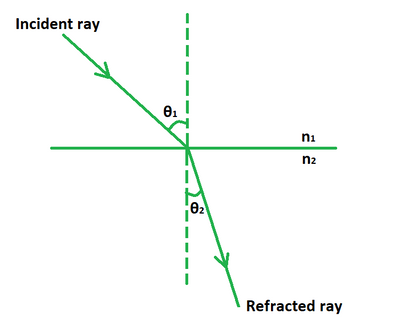
When light travels through a uniform medium like air or glass, it moves in straight lines at a constant speed. However, when light crosses the boundary between two different materials, something interesting happens: the light changes direction. This bending of light at material boundaries is called refraction, and it occurs because light travels at different speeds in different materials. Light moves fastest in a vacuum, slightly slower in air, noticeably slower in water, and even slower in glass or diamond. When a light ray enters a material where it travels more slowly, the ray bends toward the perpendicular to the surface. When it enters a material where it travels faster, the ray bends away from the perpendicular.
The relationship between the angles and the materials is described by Snell's Law, one of the fundamental principles of optics. Snell's Law states that when light crosses a boundary between two materials, the product of the refractive index and the sine of the angle remains constant. Mathematically, we write this as n₁ sin(θ₁) = n₂ sin(θ₂), where n₁ and n₂ are the refractive indices of the first and second materials, and θ₁ and θ₂ are the angles the light ray makes with the surface normal in each material. The refractive index is a dimensionless number that characterizes how much a material slows down light compared to a vacuum. Air has a refractive index very close to one, meaning light travels through air at nearly the same speed as in a vacuum.
To understand Snell's Law intuitively, imagine a car driving from a paved road onto a sandy beach at an angle. The wheels that hit the sand first will slow down while the wheels still on the pavement continue at full speed, causing the car to turn toward the perpendicular to the beach edge. Light behaves similarly when entering a slower medium. Conversely, if the car drives from sand back onto pavement, it will turn away from the perpendicular as the wheels regain speed. This mechanical analogy helps explain why light bends toward the normal when entering a denser medium and away from the normal when entering a less dense medium.
When Refraction Fails: Total Internal Reflection
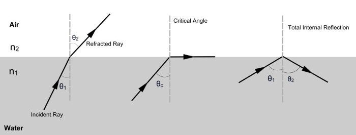
Snell's Law works beautifully when light travels from a less dense medium into a denser one, such as from air into glass. The light bends toward the normal, and there's always a valid refracted ray direction. However, something interesting happens when light travels in the opposite direction, from a denser medium into a less dense one, such as from glass into air or from water into air. In these cases, the light bends away from the normal, and at certain angles, something remarkable occurs: refraction becomes impossible, and all the light reflects back into the denser medium instead. This phenomenon is called total internal reflection, and it's responsible for many striking optical effects.
To understand why total internal reflection occurs, let's revisit Snell's Law: n₁ sin(θ₁) = n₂ sin(θ₂). When light travels from a denser medium (higher refractive index) to a less dense medium (lower refractive index), we have n₁ > n₂. Rearranging Snell's Law to solve for the refracted angle gives us sin(θ₂) = (n₁/n₂) sin(θ₁). Since n₁ > n₂, the ratio n₁/n₂ is greater than one. This means sin(θ₂) is larger than sin(θ₁), so the refracted ray bends away from the normal, making a larger angle with the normal than the incident ray did.
The problem arises when the incident angle becomes large enough that the formula would require sin(θ₂) to exceed one. Since the sine of any real angle cannot exceed one, this represents a mathematical impossibility. There is no real angle θ₂ that satisfies Snell's Law in this situation. Physically, this means the light cannot refract into the second medium at all. Instead, all the light reflects back into the first medium, as if the boundary were a perfect mirror. This is total internal reflection, and it occurs whenever the incident angle exceeds a critical angle determined by the refractive indices of the two materials.
The Fresnel Effect and Schlick's Approximation
Even when total internal reflection doesn't occur, transparent materials don't simply refract all the light that hits them. In reality, some light reflects off the surface while the rest refracts through it. The proportion of light that reflects versus refracts depends on the angle at which the light hits the surface, a phenomenon known as the Fresnel effect, named after the French physicist Augustin-Jean Fresnel, who first described it mathematically in the early 1800s. You've probably observed the Fresnel effect many times without realizing it. When you look straight through a window, you see mostly what's on the other side with only faint reflections of your room. But when you look at the same window from a steep angle, the reflections become much stronger and the window starts to look almost like a mirror.
The Fresnel effect is a fundamental property of all interfaces between materials with different refractive indices, not just transparent materials. Even metals exhibit Fresnel effects, though they're less noticeable because metals already reflect most light. For dielectric materials like glass, water, or plastic, the Fresnel effect is quite pronounced. At normal incidence (when light hits the surface straight on), only a small percentage of light reflects. For typical glass with a refractive index of 1.5, about four percent of the light reflects at normal incidence and ninety-six percent transmits through. As the angle increases and the light hits the surface more obliquely, the reflection percentage increases dramatically. At grazing angles (nearly parallel to the surface), almost one hundred percent of the light reflects, regardless of the material's refractive index.
The exact Fresnel equations that describe this behavior are somewhat complex, involving different formulas for light polarized parallel and perpendicular to the plane of incidence. For real-time rendering and ray tracing, we typically use an approximation developed by Christophe Schlick in 1994. Schlick's approximation provides a simple formula that closely matches the full Fresnel equations while being much faster to compute. The approximation is based on the observation that the reflectance varies smoothly from a base value at normal incidence to nearly one hundred percent at grazing angles, and this variation can be approximated by a polynomial function.
Schlick's approximation formula is R(θ) = R₀ + (1 - R₀)(1 - cos(θ))⁵, where R(θ) is the reflectance (the fraction of light that reflects) at angle θ, and is the reflectance at normal incidence. The base reflectance depends on the refractive indices of the two materials and is calculated as . For an air-glass interface with and , we get , confirming that about four percent of light reflects at normal incidence.
Building the Dielectric Material Class
Now that we have the mathematical tools for refraction, total internal reflection, and the Fresnel effect, we're ready to implement the dielectric material class. This class will bring together all the concepts we've discussed to create realistic transparent materials. The dielectric material needs to handle several cases: determining whether a ray is entering or exiting the material, checking for total internal reflection, applying Schlick's approximation to choose between reflection and refraction, and calculating the appropriate scattered ray direction.
Open your src/material.h file and add the dielectric class after the metal class. Make sure you've included math_utils.h at the top of the file if you haven't already. Here's the complete dielectric class:
Let's walk through this implementation step by step, understanding each decision and how it contributes to realistic glass rendering. The constructor takes a single parameter, the index of refraction, which we store in the member variable ir. We use the explicit keyword to prevent implicit conversions from double to dielectric, which is good practice for single-parameter constructors. The index of refraction characterizes the material: 1.5 for typical glass, 1.33 for water, 2.4 for diamond, and so on.
The scatter function begins by setting the attenuation to white . This represents the fact that ideal glass doesn't absorb any light as it passes through. In reality, glass does absorb some light, especially over long distances, and colored glass absorbs different wavelengths differently. However, for the thin glass objects we typically render in ray tracing, the absorption is negligible, so we use white attenuation. This means the glass doesn't change the color of light passing through it, only its direction.
Rendering Glass Objects and the Hollow Sphere Trick
With our dielectric material implemented, we're ready to create scenes featuring glass and other transparent objects. Let's set up a scene that demonstrates the various properties of dielectric materials, including refraction, reflection, and total internal reflection. We'll create several spheres with different materials to show how glass interacts with both diffuse and metallic surfaces, and we'll introduce a clever technique for creating hollow glass objects that look particularly realistic.
Open your src/main.cc file and update the scene setup section. We'll create a scene with a ground plane, a glass sphere in the center, a metal sphere on the right, and another glass sphere on the left. Here's the material and world setup:
Let's examine each material and object. The ground material is a Lambertian diffuse material with a yellowish color, the same as in previous lessons. This provides a matte surface that contrasts nicely with the shiny glass and metal spheres. The glass material is a dielectric with refractive index 1.5, which is typical for common glass. This will give us realistic glass behavior with the right amount of refraction and reflection. The metal material is a golden-colored metal with zero fuzz, creating a perfect mirror finish that will show clear reflections of the glass spheres.
The world setup includes five spheres. The first is the large ground sphere with radius one hundred, positioned below the scene to act as a flat ground plane. The second sphere is at the center of the scene with radius 0.5, made of glass. This is where things get interesting. The third sphere is also at the center of the scene, but it has a negative radius of -0.45 and is also made of glass. This negative radius creates what we call a hollow glass sphere, and it's a clever trick that produces particularly realistic glass objects.
How does a negative radius work? In our ray tracer, when we calculate ray-sphere intersections, a negative radius effectively flips the surface normal. The sphere still occupies the same space, but the normals point inward instead of outward. When we place a negative-radius sphere inside a positive-radius sphere at the same center, we create a hollow shell. Rays entering the outer sphere will eventually hit the inner sphere, but because the inner sphere's normals point inward, the ray tracer treats this as exiting the glass back into air (or rather, into the hollow interior, which we treat as air). This creates a glass bubble or hollow glass sphere.
Summary and What's Next
In this lesson, you learned how to render transparent materials like glass and water by implementing dielectric materials in your ray tracer. You explored the physics of refraction using Snell’s Law, handled total internal reflection when light cannot exit a material, and used Schlick’s approximation to simulate the Fresnel effect, which controls the balance between reflection and refraction based on viewing angle. You combined these concepts in a dielectric material class that probabilistically chooses between reflection and refraction for each ray. You also learned the hollow sphere trick to create realistic thin-walled glass objects. With diffuse, metal, and dielectric materials now implemented, your ray tracer can render a wide range of realistic scenes with complex material interactions.
Be a part of our community of 1M+ users who develop and demonstrate their skills on CodeSignal
In this lesson, you'll learn how to implement dielectric materials, which is the term we use in computer graphics for transparent materials like glass, water, and gemstones. You'll understand the physics of refraction and how to calculate refracted ray directions using Snell's Law. You'll learn about total internal reflection, a phenomenon where light cannot exit a material and instead reflects internally, creating effects like the sparkle in diamonds or the mirror-like appearance of water viewed from below the surface. You'll also implement Schlick's approximation, an efficient method for determining when light should reflect versus refract based on the viewing angle.
By the end of this lesson, you'll have implemented all three fundamental material types used in physically based rendering: diffuse materials that scatter light, metals that reflect light, and dielectrics that both reflect and transmit light. With these three material types, your ray tracer will be capable of rendering highly realistic scenes with complex material interactions. You'll be able to create images featuring glass spheres that refract and distort the objects behind them, water surfaces that reflect the sky while revealing what's beneath, and diamond-like objects that sparkle with internal reflections.
For our ray tracer, we need to implement Snell's Law in a way that calculates the refracted ray direction given an incoming ray direction, a surface normal, and the refractive indices of the two materials. Rather than working directly with angles, which would require expensive trigonometric functions, we can derive a vector formula that computes the refracted direction directly. The key insight is that we can decompose the refracted ray into components perpendicular and parallel to the surface, calculate each component separately using Snell's Law, and then combine them to get the final refracted direction.
Let's work through the mathematics step by step. Suppose we have an incoming ray with unit direction vector uv hitting a surface with unit normal n. The ray is traveling from a material with refractive index η (the Greek letter eta) into a material with refractive index η' (eta prime). We define the ratio η/η' as the relative refractive index. For example, if light is going from air (η ≈ 1.0) into glass (η' ≈ 1.5), the ratio is approximately 0.667. If light is going from glass back into air, the ratio is approximately 1.5.
The refracted ray direction can be split into two components: one perpendicular to the surface and one parallel to it. The perpendicular component is calculated as (η/η')(uv + cos(θ)n), where cos(θ) is the cosine of the angle between the incoming ray and the normal. We can compute this cosine using the dot product: cos(θ) = -uv · n. The negative sign accounts for the fact that the incoming ray typically points toward the surface while the normal points away from it. The parallel component is calculated as -√(1 - |r_perp|²)n, where r_perp is the perpendicular component we just calculated. This formula comes from the constraint that the refracted ray must be a unit vector, so the parallel and perpendicular components must satisfy the Pythagorean theorem.
Let's implement this calculation in code. Open your src/math_utils.h file and add the refract function after the existing reflect function:
The function takes three parameters: the incoming ray direction uv (which should be a unit vector), the surface normal n (also a unit vector), and the ratio of refractive indices eta_over_eta_prime. The first line calculates the cosine of the angle between the incoming ray and the normal using the dot product. We use std::fmin to clamp the result to a maximum of one, which prevents numerical errors from causing the cosine to exceed one due to floating-point precision issues. Such errors are rare but can occur when the ray is nearly parallel to the surface.
The second line calculates the perpendicular component of the refracted ray. We add the incoming direction uv to cos_theta * n, which effectively projects the incoming ray onto the plane of the surface and then scales it by the refractive index ratio. This scaling is what causes the bending: when light enters a denser medium (ratio less than one), the perpendicular component becomes smaller, bending the ray toward the normal. When light enters a less dense medium (ratio greater than one), the perpendicular component becomes larger, bending the ray away from the normal.
The third line calculates the parallel component. We use the Pythagorean theorem to find the length of the parallel component: since the refracted ray must be a unit vector, and we know the length of the perpendicular component, the parallel component's length must be the square root of one minus the perpendicular component's length squared. We use std::fabs to take the absolute value before the square root, which protects against small negative values that might arise from floating-point errors. The negative sign in front ensures the parallel component points in the correct direction relative to the normal. Finally, we multiply by the normal vector n to get the parallel component as a vector rather than just a scalar length.
The last line combines the perpendicular and parallel components to produce the final refracted ray direction. This vector will be a unit vector (or very close to one, within floating-point precision) pointing in the direction the light travels after refraction. The beauty of this vector formulation is that it handles all the trigonometry internally without requiring explicit angle calculations, making it both efficient and numerically stable.
You can observe total internal reflection in everyday situations. If you're underwater in a swimming pool and look up toward the surface at a steep angle, you'll see a mirror-like reflection of the pool bottom rather than seeing through the surface to the air above. The water surface acts as a perfect mirror for light rays hitting it from below at angles beyond the critical angle. Similarly, optical fibers use total internal reflection to guide light over long distances. Light entering one end of the fiber bounces repeatedly off the fiber's inner surface through total internal reflection, traveling down the fiber with minimal loss even as the fiber bends and curves.
The critical angle can be calculated by setting sin(θ₂) = 1 in Snell's Law, which gives sin(θ_critical) = n₂/n₁. For the water-air boundary, with water having a refractive index of about 1.33 and air about 1.0, the critical angle is arcsin(1.0/1.33) ≈ 48.6 degrees. Any ray hitting the water surface from below at an angle greater than 48.6 degrees from the normal will undergo total internal reflection. For glass with a refractive index of 1.5, the critical angle is about 41.8 degrees. Materials with higher refractive indices have smaller critical angles, which is one reason why diamonds sparkle so brilliantly: their high refractive index (about 2.4) gives them a critical angle of only about 24.4 degrees, causing much of the light entering a diamond to reflect internally multiple times before exiting.
In our ray tracer implementation, we need to detect when total internal reflection should occur and handle it appropriately. Looking back at our refract function, the condition for total internal reflection can be detected by checking whether the perpendicular component of the refracted ray would have a length greater than one. Recall that we calculate the parallel component's length as √(1.0 - r_out_perp.length_squared()). If r_out_perp.length_squared() exceeds one, the square root would be taking the square root of a negative number, which is undefined for real numbers. This is the mathematical signature of total internal reflection.
We can detect this condition before calling the refract function by checking whether sin(θ) would exceed one. From Snell's Law, we know that sin(θ₂) = (η/η') sin(θ₁). We can calculate sin(θ₁) from cos(θ₁) using the identity sin²(θ) + cos²(θ) = 1, which gives us sin(θ₁) = √(1 - cos²(θ₁)). If (η/η') sin(θ₁) > 1, then total internal reflection occurs and we should reflect the ray instead of refracting it. This check will be implemented in our dielectric material's scatter function, where we'll use the existing reflect function instead of refract when total internal reflection occurs.
The presence of total internal reflection adds visual richness to transparent objects. A glass sphere, for example, will show both refracted views of objects behind it and reflected views of objects in front of it, with the balance between refraction and reflection depending on the viewing angle. The internal surfaces of hollow glass objects can act as mirrors due to total internal reflection, creating complex and beautiful light patterns. When you implement the dielectric material in the next sections, you'll see how total internal reflection contributes to the realistic appearance of glass and other transparent materials.
The fifth power term (1 - cos(θ))⁵ is what makes the reflectance increase rapidly as the angle approaches ninety degrees (grazing incidence). When the light hits straight on, θ = 0, so cos(θ) = 1, and the term becomes zero, giving us R(0) = R₀. As the angle increases, cos(θ) decreases, making (1 - cos(θ)) increase. The fifth power amplifies this effect, causing the reflectance to rise sharply at large angles. At θ = 90 degrees (grazing incidence), cos(θ) = 0, so the term becomes one, giving us R(90°) = R₀ + (1 - R₀) = 1, meaning one hundred percent reflection.
Let's implement Schlick's approximation in our math_utils.h file. Add this function after the refract function:
The function takes two parameters: cosine is the cosine of the angle between the ray and the normal, and ref_idx is the refractive index of the material we're entering (assuming we're coming from air with refractive index 1.0). The first two lines calculate R₀. We compute (1 - ref_idx) / (1 + ref_idx) and then square it by multiplying it by itself. This is slightly more efficient than using std::pow(r0, 2) and makes the code clearer. The final line implements the full Schlick formula, using std::pow(1 - cosine, 5) to compute the fifth power term.
One important detail about using Schlick's approximation in a ray tracer is that we need to be careful about which refractive index to use. The formula as written assumes we're going from air (or vacuum) into the material. When a ray is exiting the material back into air, we need to adjust our approach. The key insight is that we should always use the refractive index ratio in a consistent way. When the ray is entering the material, we use the material's refractive index directly. When the ray is exiting, we use the reciprocal of the refractive index. This ensures that the Fresnel effect behaves correctly regardless of which direction the light is traveling.
In practice, we'll use Schlick's approximation to make a probabilistic decision about whether a ray should reflect or refract. We'll generate a random number between zero and one, and if this random number is less than the reflectance calculated by Schlick's approximation, we'll reflect the ray. Otherwise, we'll refract it. This probabilistic approach is physically accurate when averaged over many samples, which is exactly what our antialiasing with multiple samples per pixel provides. Some rays will reflect, some will refract, and the final pixel color will be the average of all these samples, correctly representing the Fresnel effect.
(1.0, 1.0, 1.0)
The next line determines the refraction ratio, and this is where we handle the distinction between rays entering and exiting the material. Recall from Lesson 2 that the hit_record includes a front_face boolean that tells us whether the ray hit the outside or inside of the surface. When front_face is true, the ray is hitting the outside of the object, traveling from air into the material. In this case, the refraction ratio should be 1.0 / ir, representing the transition from air (refractive index 1.0) to the material (refractive index ir). When front_face is false, the ray is hitting the inside of the object, traveling from the material back into air. In this case, the refraction ratio should be ir / 1.0, which simplifies to just ir.
We then normalize the incoming ray direction and calculate the cosine of the angle between the ray and the normal. The std::fmin clamps the result to a maximum of one, protecting against numerical errors. We also calculate the sine of the angle using the trigonometric identity sin²(θ) + cos²(θ) = 1, which gives us sin(θ) = √(1 - cos²(θ)). We need the sine to check for total internal reflection.
The total internal reflection check is straightforward: if refraction_ratio * sin_theta > 1.0, then Snell's Law would require the sine of the refracted angle to exceed one, which is impossible. In this case, we set the boolean cannot_refract to true. When this happens, we must reflect the ray rather than refract it. This is the total internal reflection we discussed earlier, and it's essential for realistic glass rendering.
Even when refraction is mathematically possible, we don't always refract. We use Schlick's approximation to determine the probability of reflection based on the viewing angle. We call schlick_reflectance(cos_theta, refraction_ratio) to get the reflectance value, then compare it to a random number generated by random_double(). If the random number is less than the reflectance, we reflect the ray. Otherwise, we refract it. This probabilistic approach correctly implements the Fresnel effect: at normal incidence, most rays refract and only a few reflect. At grazing angles, most rays reflect and only a few refract.
The actual reflection or refraction is handled by calling either the reflect or refract function we implemented earlier in math_utils.h. Both functions return a direction vector, which we use to create the scattered ray starting from the hit point. Notice that we always return true from the scatter function. Unlike metals, which can absorb rays that scatter below the surface, dielectrics always scatter rays (either through reflection or refraction), so we never absorb the ray completely.
One subtle but important detail is that we're using the refraction ratio directly in the Schlick approximation. This works correctly because when the ray is entering the material, the refraction ratio is less than one (specifically, 1.0 / ir), and when the ray is exiting, the refraction ratio is greater than one (specifically, ir). The Schlick approximation handles both cases correctly with this approach, giving us the right reflectance probability regardless of which direction the ray is traveling.
Let's trace through what happens when a ray hits a glass sphere. First, the ray hits the outside of the sphere. The front_face is true, so we use refraction ratio 1.0 / 1.5 ≈ 0.667. We check for total internal reflection, but since we're going from air into glass (less dense to more dense), total internal reflection cannot occur. We apply Schlick's approximation. If the ray hits at a steep angle, there's a good chance it reflects. If it hits more perpendicularly, it will likely refract. If it refracts, it enters the glass and continues until it hits the inside of the sphere. Now front_face is false, so we use refraction ratio 1.5. This time, total internal reflection is possible if the ray hits at a steep enough angle. If total internal reflection doesn't occur, we again apply Schlick's approximation to decide between reflection and refraction. If the ray refracts, it exits the glass back into air.
This back-and-forth between reflection and refraction, combined with the angle-dependent behavior from Schlick's approximation, creates the complex and realistic appearance of glass. Some rays pass straight through with minimal bending. Some rays reflect off the outer surface. Some rays enter the glass, reflect internally, and exit at a different point. The combination of all these paths, averaged over many samples per pixel, produces the characteristic look of transparent materials.
Why is this useful? Solid glass spheres can look a bit odd because they're so thick. Light refracts when entering, travels through a lot of glass, and refracts again when exiting. The result can look overly distorted. Hollow glass spheres look more like real glass objects such as glass ornaments, light bulbs, or glass bubbles. The thin shell of glass produces more subtle refraction while still showing all the interesting optical effects. The hollow interior also allows for interesting internal reflections due to total internal reflection on the inner surface.
The fourth sphere is positioned to the right with radius 0.5, made of the golden metal material. This sphere will show clear reflections of the glass spheres and the ground, demonstrating how different materials interact in the scene. The fifth sphere is positioned to the left with radius 0.5, made of glass. This gives us two glass spheres to compare: one hollow (in the center) and one solid (on the left). You'll be able to see the difference in how they refract and reflect light.
When you render this scene, you'll notice several interesting effects. The center hollow glass sphere will show subtle distortion of the background, with the yellow ground and blue sky visible through it but slightly bent. You'll see reflections on the sphere's surface, especially at grazing angles where the Fresnel effect makes the glass more mirror-like. The solid glass sphere on the left will show stronger distortion because light passes through more glass. The metal sphere on the right will show clear reflections of the glass spheres, and you might even see the glass spheres reflecting each other.
One particularly striking effect is the bright spot or caustic that often appears on the ground beneath glass spheres. This happens because the glass sphere acts like a lens, focusing light rays onto a small area. Our path tracer captures this effect naturally through the refraction calculations. Multiple rays that would have hit different parts of the ground all get bent by the glass to hit the same spot, making that spot appear brighter. This is the same effect that allows you to start a fire with a magnifying glass on a sunny day.
When you compile and run this program, the render will take about the same amount of time as previous lessons. Dielectric materials don't add significant computational cost compared to metals or diffuse materials. Each material type requires some random number generation and vector calculations, but they're all roughly equivalent in complexity. The main factor affecting render time is still the number of samples per pixel and the maximum ray depth.
You can experiment with different refractive indices to simulate different materials. Try changing the glass material to use 1.33 for water, 2.4 for diamond, or other values. Higher refractive indices produce more dramatic refraction and smaller critical angles for total internal reflection, leading to more internal reflections and sparkle. You can also try different sphere arrangements, add more glass objects, or combine glass with various metals and diffuse materials to create complex scenes with rich material interactions.