Loading and Applying Textures
Introduction
Welcome back to Interactive Camera and Texturing! We've reached lesson 3, marking significant progress in our journey through interactive 3D graphics. In our previous lessons, we built a robust camera system that responds to both movement and look controls, allowing us to navigate through 3D space with complete freedom. Now, we're ready to take the next major step: bringing our 3D scenes to life with textures. Texturing transforms plain geometric surfaces into visually rich objects that can represent real-world materials, patterns, or artistic designs. Today, we'll learn how to load external images, apply them to 3D geometry, and integrate texture mapping seamlessly with our existing camera system to create compelling visual experiences.
Understanding Texture Mapping Fundamentals
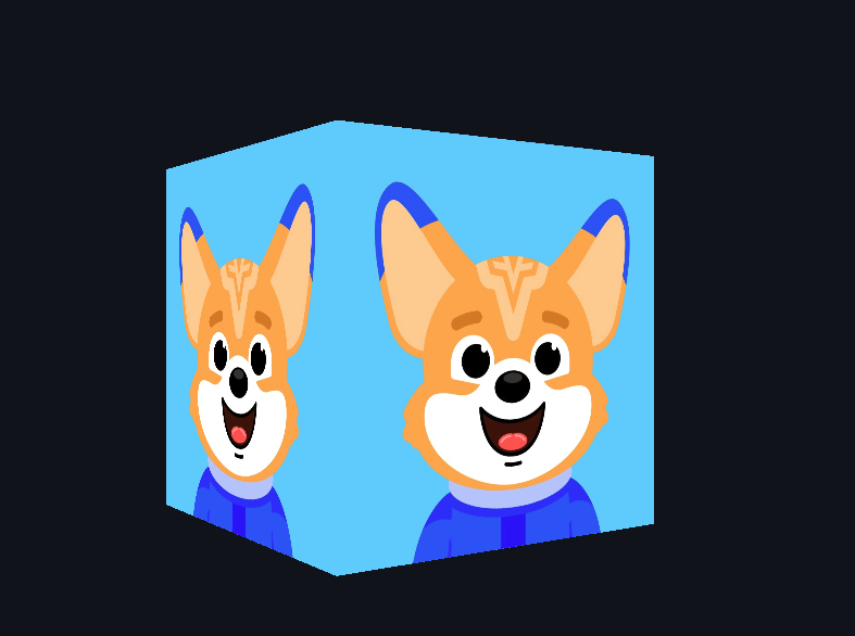
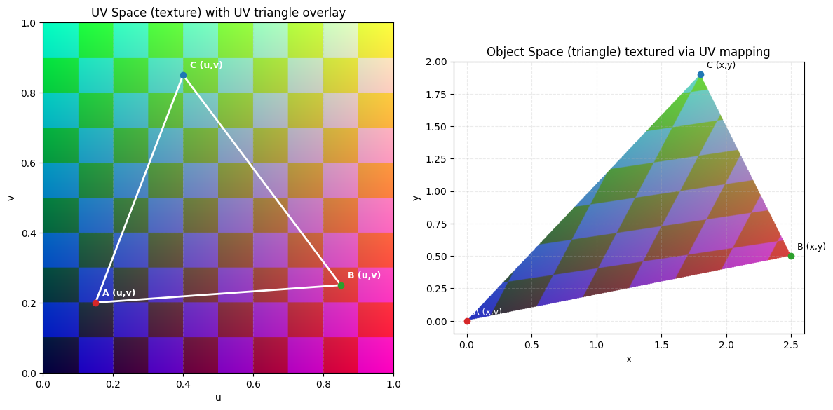
Texture mapping is the process of applying 2D images onto 3D surfaces to create the illusion of detail and material properties. Think of it like wrapping a photograph around a box: the image gets stretched and positioned to cover the geometric surface. In computer graphics, we accomplish this through UV coordinates (also called ST coordinates), which create a mapping between 2D image pixels and 3D surface points. The term UV represents the coordinate system of the texture image, where U is the horizontal axis and V is the vertical axis. They are labeled this way to avoid confusion with other coordinate axes. These coordinates typically range from 0.0 to 1.0, where (0,0) represents the bottom-left corner of the image and (1,1) represents the top-right corner. By assigning UV coordinates to each vertex of our geometry, we tell the GPU exactly how to stretch and position the texture across our 3D surfaces.
Updating Vertex Data for Texture Coordinates
To enable texture mapping, we must expand our vertex data to include UV coordinates alongside position information. Previously, our vertex data included RGB color values for each vertex to specify its color. Now, we replace those RGB values with UV coordinates, which will be used to map the texture image onto the geometry. Our enhanced vertex array now contains five values per vertex:
Each vertex now includes three position values (X, Y, Z) followed by two UV values (U, V). For the front face, notice how the UV coordinates form a square mapping: bottom-left (0,0), bottom-right (1,0), top-right (1,1), and top-left (0,1). This creates a direct correspondence between the texture image and the face geometry, ensuring the image appears correctly oriented on the surface.