Welcome back to our Advanced Geometry and Model Loading course! We've reached the exciting conclusion of our journey together, having mastered face culling optimizations, sophisticated 3D model loading with tiny_obj_loader, and immersive environmental rendering through cubemap skyboxes. Each lesson has built upon the last, creating increasingly sophisticated rendering systems that bring professional-quality graphics within your reach.
In this final lesson, we're unlocking a powerful stage of the graphics pipeline that has been working behind the scenes throughout our entire course: the geometry shader. While our previous work focused on transforming and rendering existing geometry, we now venture into the fascinating realm of procedural geometry generation, where we can dynamically create new geometric primitives directly on the GPU during rendering.
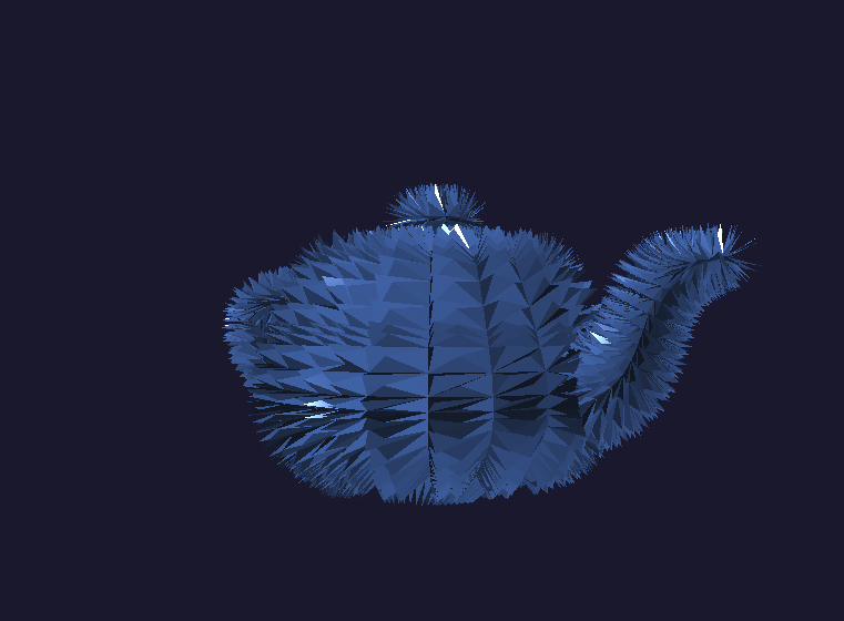
We'll implement a stunning crystallization effect that transforms our familiar teapot model into a dynamic, crystal-covered surface with animated growth patterns. This technique demonstrates how geometry shaders enable effects impossible with traditional vertex and fragment processing alone: generating entirely new triangles, creating particle systems, producing wireframe overlays, and building complex procedural structures that respond to real-time parameters. By lesson's end, you'll command the complete OpenGL graphics pipeline, equipped with the knowledge to create sophisticated visual effects that rival those found in modern games and interactive applications.
Throughout our previous lessons, we've worked extensively with vertex and fragment shaders, treating them as the primary programmable stages of the graphics pipeline. However, we've actually been missing one crucial step that OpenGL has been handling automatically behind the scenes: the geometry processing stage that occurs between vertex transformation and rasterization.
Until now, OpenGL has been quietly performing a default geometry processing operation for us. When we submitted triangles through our vertex shaders, the graphics hardware automatically passed them through an invisible geometry stage that simply forwarded each triangle unchanged to the rasterizer. This automatic behavior worked perfectly for our previous lessons because we only needed to transform existing geometry, not create new primitives.
The geometry shader gives us direct control over this previously hidden pipeline stage, allowing us to intercept primitives after vertex processing and before rasterization. This positioning grants us remarkable creative power: we can examine entire primitives (not just individual vertices), generate multiple output primitives from single inputs, or even discard primitives entirely based on dynamic criteria.
The geometry shader operates on complete geometric primitives rather than individual vertices, fundamentally changing how we can manipulate 3D data. While vertex shaders process one vertex at a time in isolation, geometry shaders receive entire triangles, lines, or points as input and can generate multiple output primitives in response.
This primitive-level processing enables effects that would be impossible with vertex-only manipulation. Consider creating a crystal growth effect: a vertex shader could move individual vertices, but only a geometry shader can examine a triangle's surface normal and generate entirely new triangular facets extending outward from that surface. The geometry shader bridges the gap between per-vertex transformations and per-pixel fragment processing.
Our geometry shader declaration reveals its unique characteristics. The layout(triangles) in specification indicates we expect to receive complete triangles as input primitives from the vertex shader stage. The layout(triangle_strip, max_vertices = 18) out declaration defines our output format: we'll generate triangle strips with a maximum of 18 vertices per input primitive, allowing us to create multiple new triangles from each original triangle.
The geometry shader's input and output specifications require careful coordination with the surrounding pipeline stages:
Input variables arrive as arrays containing data for each vertex of the input primitive. Since we specified triangles as input, each array contains exactly three elements representing the triangle's vertices. These arrays provide access to the complete primitive data that the vertex shader computed, enabling us to perform calculations that consider the entire triangle's properties rather than individual vertex characteristics.
Output variables follow the standard single-value format because we output individual vertices for the new primitives we generate. The gCrystalFactor represents a new attribute we're introducing to distinguish between original geometry and our procedurally generated crystal structures, allowing the fragment shader to apply different materials accordingly.
Our crystal generation algorithm demonstrates the geometry shader's power to create entirely new geometric structures while maintaining the original model's integrity:
We begin by preserving the original triangle to ensure our base teapot remains intact. The EmitVertex() function outputs a single vertex with the specified attributes, while EndPrimitive() signals the completion of one output primitive. This approach guarantees that, regardless of our crystal generation success, the underlying model structure remains visible and correctly rendered.
The gCrystalFactor of 0.0 identifies these vertices as original geometry, enabling the fragment shader to apply appropriate base materials to distinguish them from the procedurally generated crystals.
The procedural crystal creation involves calculating geometric properties from the input triangle to determine where and how crystals should grow:
This algorithm computes the triangle's geometric center and average normal direction, then projects outward along the normal to create a crystal tip position. The pulseFactor introduces time-based animation using a sinusoidal function, making the crystals grow and shrink rhythmically as the application runs. The mathematical relationship creates smooth, periodic crystal growth that adds visual interest without being distracting.
Each crystal consists of triangular facets connecting adjacent edges of the base triangle to the projected crystal tip:
This loop systematically creates three triangular faces, each connecting two consecutive base vertices to the crystal tip position. The cross product calculation generates proper face normals for lighting calculations, ensuring the crystal facets integrate seamlessly with our existing lighting system. Each facet represents a face of a triangular pyramid, creating the characteristic angular appearance of crystal formations.
The coordinate space transformations ensure that our procedurally generated geometry aligns correctly with the existing model data and camera transformations, maintaining consistency with the vertex shader's transformation pipeline.
Geometry shader integration requires an extended shader creation function that handles the additional shader stage:
The C++ integration follows the familiar pattern of shader compilation and linking, with the addition of the GL_GEOMETRY_SHADER stage between vertex and fragment processing. The extended error checking ensures that geometry shader compilation failures are caught and reported appropriately, maintaining the robust error handling we've established throughout our course.
Our main rendering loop requires minimal changes to accommodate the geometry shader, as it executes automatically whenever we render geometry with the enhanced shader program.
Our vertex shader requires modifications to support the geometry shader's input requirements:
The vertex shader now outputs additional data streams beyond the standard gl_Position. The vPosition output provides model space coordinates that the geometry shader needs for calculating triangle centers and crystal placement. The vNormal and vWorldPos outputs supply the geometric information necessary for proper crystal orientation and lighting calculations.
This expanded vertex output demonstrates how the geometry shader stage affects the entire pipeline design, requiring coordination between all shader stages to ensure proper data flow and geometric consistency.
The fragment shader incorporates material differentiation based on the gCrystalFactor attribute from our geometry shader:
This material system creates visual distinction between the original model geometry and the procedurally generated crystal structures. The base teapot maintains a dark, metallic appearance, while the crystals exhibit a bright, reflective blue coloration with enhanced specular highlights. The enhanced specular calculation for crystal surfaces creates the convincing appearance of faceted, reflective crystal formations that catch and reflect light dramatically differently from the underlying metallic surface.
When we execute the complete implementation, the results showcase the remarkable creative potential of geometry shader programming. The application displays a mesmerizing crystallized teapot, where each original triangle surface has spawned dynamic crystal formations that pulse rhythmically with time-based animation. The crystals maintain perfect geometric alignment with the underlying surface normals, creating a natural crystal growth pattern that follows the teapot's curved contours.
The real-time animation demonstrates the geometry shader's ability to create complex, dynamic effects entirely on the GPU without any CPU-based geometry processing. As you navigate around the scene using the familiar camera controls from our previous lessons, the crystal formations catch and reflect light from different angles, creating a captivating interplay between the dark metallic base surface and the brilliant crystalline growths.
We have successfully implemented a sophisticated geometry shader system that demonstrates the full power of procedural geometry generation directly within the GPU pipeline. Your implementation showcases how the geometry shader stage enables effects impossible with traditional vertex and fragment processing alone, from dynamic crystal growth to complex surface modifications that respond to real-time parameters. The techniques you've mastered represent the foundation for advanced procedural effects, including particle systems, tessellation enhancement, and complex geometric transformations that define modern real-time graphics.
Throughout this course, we've built a comprehensive understanding of the complete OpenGL graphics pipeline, from fundamental optimizations like face culling, through sophisticated model loading and environmental rendering, to the advanced procedural techniques you've just mastered. The upcoming practice exercises will give you the opportunity to experiment with your own procedural geometry ideas and discover the limitless creative possibilities that emerge when you command every stage of the modern graphics pipeline.
