In the previous lesson, you built a camera system that gives you complete control over position, orientation, and field of view. You can place your camera anywhere in the scene, point it at any target, and adjust how much of the scene fits in the frame. However, there's one aspect of real cameras that our current implementation doesn't capture: selective focus.
Right now, your ray tracer uses what's called a pinhole camera model. Every object in your scene appears perfectly sharp, regardless of how close or far it is from the camera. While this is mathematically simple and computationally efficient, it doesn't match how real cameras work. When you take a photograph with an actual camera, only objects at a certain distance appear sharp. Objects closer to or farther from this focal plane become progressively blurred. This effect is called depth of field, and it's one of the most powerful tools in photography for directing viewer attention and creating a sense of depth.
In this lesson, you'll transform your pinhole camera into a more realistic lens-based camera by implementing the thin-lens approximation. You'll add two new parameters to your camera class: defocus_angle, which controls the size of the lens aperture and determines how much blur occurs, and focus_dist, which specifies the distance at which objects appear perfectly sharp. By the end of this lesson, you'll be able to create images where your main subject stands out sharply against a beautifully blurred background, just like in professional portrait photography.
The implementation builds directly on the camera infrastructure you created in the previous lesson. You'll modify the get_ray() function to sample ray origins from a circular disk rather than a single point, and you'll see how this simple change produces realistic depth of field effects through the power of Monte Carlo sampling.
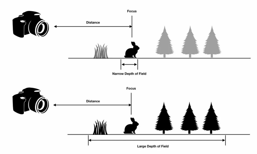
Depth of field refers to the range of distances in a scene that appear acceptably sharp in an image. When you focus a real camera on a subject, there's a specific distance — the focal plane — where objects appear perfectly sharp. Objects at this exact distance are in perfect focus. However, objects closer to or farther from the camera than this focal plane become progressively blurred. The amount of blur increases with distance from the focal plane.
This effect occurs because real cameras use lenses with finite apertures. Light from a single point in the scene doesn't converge to a single point on the camera sensor unless that point lies exactly on the focal plane. For points not on the focal plane, light spreads out into a small circle on the sensor, creating blur. The size of this circle — called the circle of confusion — determines how blurred the point appears.
Consider portrait photography as a real-world example. When photographing a person, you typically focus on their eyes. The eyes appear sharp and detailed, drawing the viewer's attention. The person's face, being at roughly the same distance, also appears sharp. However, the background — perhaps trees or buildings several meters behind the subject — appears soft and blurred. This blur helps separate the subject from the background, making the portrait more visually appealing and directing attention to the person rather than distracting background elements.
Macro photography demonstrates an extreme case of shallow depth of field. When photographing a small insect or flower from very close range, the depth of field might be only a few millimeters. The insect's eye might be perfectly sharp while its antennae, just slightly closer to the camera, appear blurred. This creates a dreamy, artistic effect that emphasizes the tiny scale of the subject.
On the opposite end of the spectrum, landscape photography often aims for deep depth of field. Landscape photographers typically want everything from the foreground rocks to the distant mountains to appear sharp. They achieve this by using a small aperture, which increases the depth of field and keeps more of the scene in focus.
Real camera lenses are complex optical systems with multiple glass elements, each with carefully designed curvatures and spacings. Simulating the actual path of light through such a system would require detailed ray tracing through each lens element, accounting for refraction, aberrations, and other optical phenomena. This level of detail is unnecessary for most rendering applications and would be computationally expensive.
Instead, we use the thin-lens approximation, a simplified model that captures the essential behavior of a lens system without the complexity. The thin-lens model treats the entire lens system as if it were an infinitely thin lens at a single plane. Despite this simplification, it produces realistic depth of field effects that are visually indistinguishable from more complex models for most purposes.
The thin-lens approximation is controlled by two key parameters. The first is focus distance (focus_dist), which specifies the distance from the camera to the focal plane. Objects at exactly this distance from the camera will appear perfectly sharp in the rendered image. Think of this as where you're "focusing" the camera — if you're photographing a person standing three meters away, you'd set the focus distance to three meters.
The second parameter is defocus angle (defocus_angle), which represents the size of the lens aperture. In real cameras, the aperture is the opening that controls how much light enters the lens, typically measured in f-stops. A larger aperture (smaller f-number like f/1.8) creates more blur, while a smaller aperture (larger f-number like f/16) creates less blur. In our implementation, we use the defocus angle instead of f-stops because it's more intuitive for our geometric model. A larger defocus angle means a larger aperture and more blur.
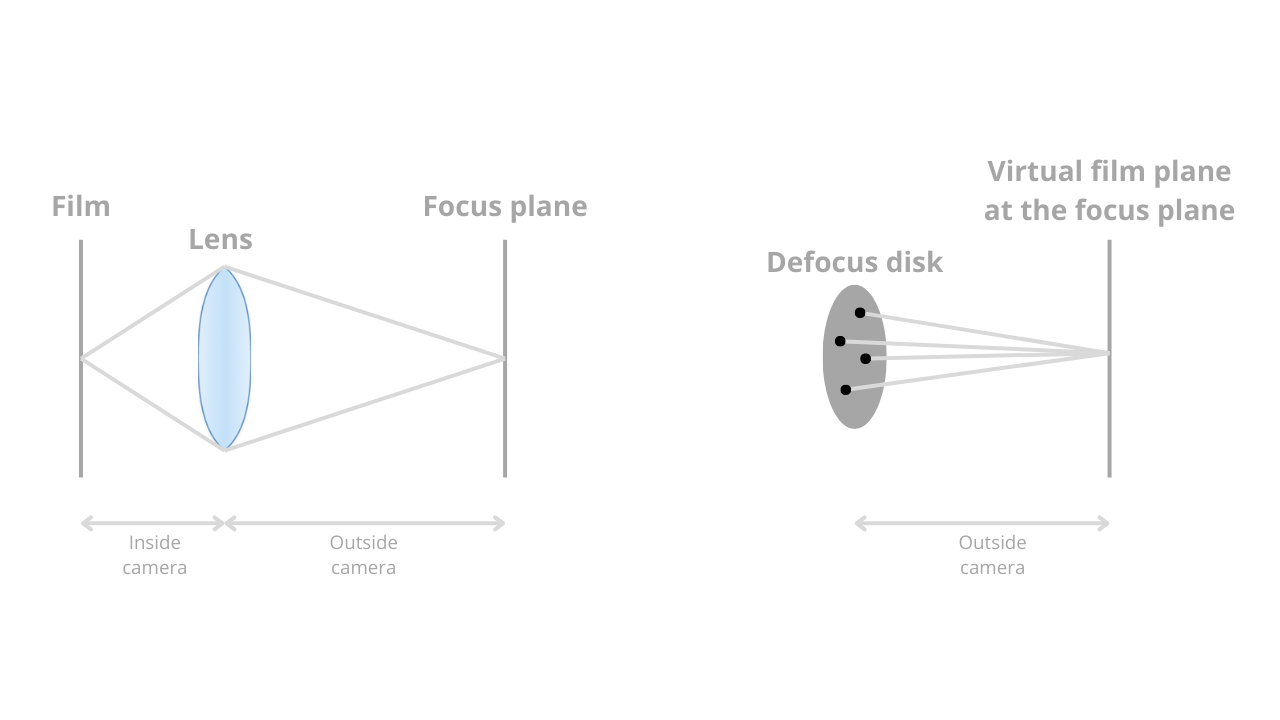
These two parameters work together to define the geometry of what we call the defocus disk. The defocus disk is a circular region in the plane of the camera from which we'll sample ray origins. The radius of this disk depends on both the focus distance and the defocus angle. Specifically, the radius equals the focus distance multiplied by the tangent of half the defocus angle. This relationship comes from basic trigonometry — imagine a cone extending from the camera center, with the defocus angle as the cone's opening angle and the focus distance as the cone's height.
The fundamental difference between a pinhole camera and a lens-based camera lies in where rays originate. In the pinhole camera model you implemented in the previous lesson, all rays originate from a single point: the camera center. When you call get_ray(i, j) for a particular pixel, the function creates a ray that starts at center and points toward a sample point on the viewport. Every ray for every pixel starts from the same location.
In a lens-based camera, rays originate from different points across a circular disk — the defocus disk we discussed in the previous section. Instead of all rays starting at the camera center, each ray starts at a random point on this disk. This is the key to creating depth of field effects. The disk lies in the plane of the camera, perpendicular to the viewing direction, and its size is determined by the defocus angle and focus distance.
To sample points uniformly across this circular disk, we use a helper function called random_in_unit_disk(). This function generates random 2D points that lie within a unit circle (a circle with radius 1). The implementation uses rejection sampling: it repeatedly generates random points in a square region from -1 to +1 in both x and y, and keeps only those points that fall within the unit circle. When a point's distance from the origin is less than 1, we know it's inside the circle and we return it.
Here's how random_in_unit_disk() works in the vec3.h file:
The function creates a 3D vector with random x and y components between -1 and +1, and a z component of 0 (since we're sampling in a 2D disk). It then checks if the point lies within the unit circle by testing if its squared length is less than 1. If the point is outside the circle, the loop continues and generates a new random point. Once a valid point is found, the function returns it. Note that we use length_squared() instead of to avoid the expensive square root operation — we only need to compare distances, not compute exact lengths.
Now let's implement the defocus disk in your camera class. You'll add the two new parameters we discussed, compute the geometry of the defocus disk during camera initialization, and modify the ray generation function to sample from this disk. The changes are relatively small but produce a dramatic visual effect.
First, add the defocus parameters to your camera class. In camera.h, you'll see these new member variables alongside the existing camera parameters:
The defocus_angle is specified in degrees and represents the angle of the cone of rays emanating from the camera. A typical value might be between 0.1 and 2.0 degrees — small angles produce subtle blur, while larger angles create more dramatic effects. The focus_dist is specified in world units and represents the distance from the camera to the focal plane. In the example above, objects 3.4 units away from the camera will appear sharp.
During camera initialization, you need to compute the geometry of the defocus disk. This happens in the initialize() function after you've set up the camera coordinate system. The defocus disk is defined by two vectors, defocus_disk_u and defocus_disk_v, which span the disk in the camera's coordinate system:
The defocus radius calculation uses trigonometry. Imagine a right triangle where the camera center is at one vertex, the edge of the defocus disk is at another vertex, and the distance between them is the focus distance. The angle at the camera is half the defocus angle (since the full angle spans from one edge of the disk to the other, passing through the center). The tangent of this half-angle equals the opposite side (the defocus radius) divided by the adjacent side (the focus distance). Therefore, multiplying the focus distance by the tangent gives us the defocus radius.
In this lesson, you've transformed your pinhole camera into a realistic lens-based camera capable of producing depth of field effects. You started by understanding what depth of field means and why it's valuable — how it helps direct viewer attention, adds realism, and creates artistic effects similar to those in photography and cinematography.
You learned about the thin-lens approximation, a simplified model that captures the essential behavior of real camera lenses without complex optical calculations. This model is controlled by two parameters: the focus distance, which determines where objects appear sharp, and the defocus angle, which controls how much blur occurs for out-of-focus objects. Together, these parameters define the geometry of the defocus disk, a circular region from which rays originate.
The implementation required adding these parameters to your camera class, computing the defocus disk geometry during initialization, and modifying the ray generation function to sample ray origins from the disk. The key insight is that rays for a given pixel all point toward the same location on the focal plane but originate from different points on the defocus disk. This causes rays to converge for objects at the focus distance (producing sharp images) but to diverge for objects at other distances (producing blur).
You also saw how the random_in_unit_disk() function enables uniform sampling across the circular defocus disk, and how Monte Carlo integration — taking many samples per pixel and averaging them — produces the final blurred image. Objects on the focal plane appear sharp because all samples contribute the same color, while objects off the focal plane appear blurred because samples contribute different colors that get averaged together.
In the upcoming practice exercises, you'll experiment with different values of defocus_angle and focus_dist to see how they affect your rendered images. You'll try focusing on different objects in your scene, adjusting the aperture size to control blur intensity, and comparing the results to the pinhole camera model. You'll also explore artistic applications, such as using shallow depth of field to isolate a subject or deep depth of field to keep an entire scene sharp.
This completes your advanced camera system. You now have full control over camera position, orientation, field of view, and depth of field. These tools give you the flexibility to create compelling images that match your artistic vision, whether you're aiming for photorealistic renders or stylized artistic effects. The camera system you've built is sophisticated enough for professional-quality rendering work, and the techniques you've learned form the foundation of modern physically based rendering systems.
