Welcome to your first lesson in digital logic and circuits. In this course, you will learn how computers and electronic devices use simple building blocks to perform complex tasks. At the heart of all digital circuits is the binary system, which uses only two values: 0 and 1. Understanding these values is the first step in designing and working with logic gates and circuits.
In this lesson, you will learn what 0 and 1 mean in digital logic, how circuits use inputs and outputs, and how to get started with the CodeSignal simulator. By the end, you will be ready to practice building your own simple circuits.
In digital circuits, everything comes down to two values: 0 and 1. These are called binary values.
0usually means "off," "false," or "low voltage."1usually means "on," "true," or "high voltage."
Think of a light switch as a real-world example:
- When the switch is off, the light is not shining. This is like a
0. - When the switch is on, the light shines. This is like a
1.
| Binary Value | Meaning in Circuits | Real-World Example |
|---|---|---|
0 | Off / False / Low | Light switch is off |
1 | On / True / High | Light switch is on |
In digital logic, every signal, button, or wire can only be in one of these two states at any time. This makes it easy for circuits to make decisions and process information.
The binary system is a way of representing numbers using only two digits: 0 and 1. This is different from the decimal system, which uses ten digits (0 to 9). In binary, each place value represents a power of 2, instead of a power of 10.
Here’s how you can represent numbers in binary:
- The rightmost digit is the "ones" place (2⁰).
- The next digit to the left is the "twos" place (2¹).
- The next is the "fours" place (2²), and so on.
For example, the binary number 101 means:
- 1 × 2⁰ (which is 1)
- 0 × 2¹ (which is 0)
- 1 × 2² (which is 4)
So, 101 in binary is equal to 1 + 0 + 4 = 5 in decimal.
| Binary | Calculation | Decimal |
|---|---|---|
| 0 | 0 | 0 |
| 1 | 1 | 1 |
| 10 | 1×2 + 0×1 = 2 | 2 |
| 11 | 1×2 + 1×1 = 3 | 3 |
| 100 | 1×4 + 0×2 + 0×1 = 4 | 4 |
| 101 | 1×4 + 0×2 + 1×1 = 5 | 5 |
This is how computers and digital circuits count and store information—using only 0s and 1s.
Every circuit has inputs and outputs.
- Inputs are signals or values that go into a circuit. They are like questions you ask the circuit.
- Outputs are the results or answers the circuit gives you.
Let’s look at a simple example:
Imagine you have a button and a light bulb connected in a circuit.
- The button is the input. You can press it (
1) or not press it (0). - The light bulb is the output. It turns on (
1) if the button is pressed and stays off (0) if the button is not pressed.
| Button (Input) | Light Bulb (Output) |
|---|---|
0 (not pressed) | 0 (off) |
1 (pressed) | 1 (on) |
Explanation:
When you press the button, you send a 1 ("on") signal to the circuit, and the light bulb turns on. If you do not press the button, the signal is 0 ("off"), and the light bulb stays off. This simple relationship between input and output is the foundation of all digital circuits.
Now that you know what 0 and 1 mean and how inputs and outputs work, let’s look at how you can build circuits using the Logic Simulator.
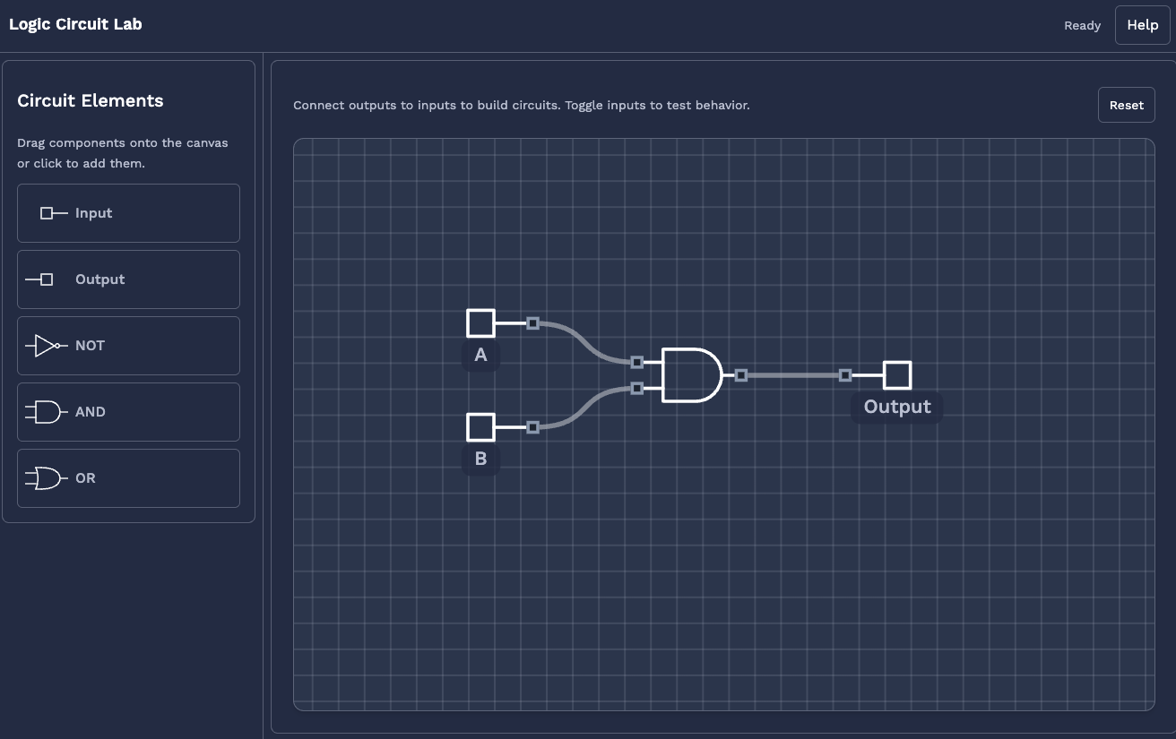
Here’s how you can get started:
-
Placing a Gate:
In the simulator, you can drag and drop different logic gates onto your workspace. For now, try placing a simple gate, like aswitch(which acts as an input) and alight(which acts as an output). -
Give them a name Right click any gate to open a small menu, where you can change properties of the gate such as the name and rotation.
-
Connecting With Wires:
Click and drag from the output of the switch to the input of the light. This creates a wire that carries the signal.
In this lesson, you learned:
- What binary values (
0and1) mean in digital logic. - How to represent numbers in binary
- The difference between inputs and outputs in a circuit.
- How to use the Logic Simulator to place gates and connect them with wires.
You are now ready to practice these basics. In the next section, you will get hands-on experience building simple circuits using the simulator. This will help you become comfortable with the tools and concepts before moving on to more complex logic gates and circuit designs. Good luck, and have fun experimenting!
